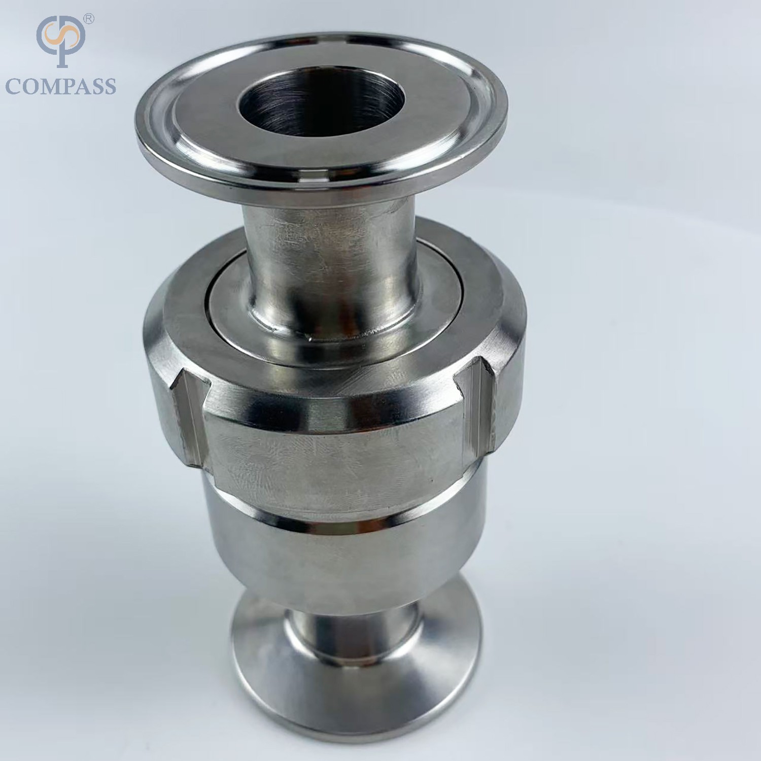
Process fluid management in hygienic environments leaves zero room for error. Improperly installed valves cause cross-contamination, destroy expensive pumps, and force massive operational downtime. Even premium-grade components fail, leak, or harbor bacteria if you miscalculate fundamental integration parameters. Piping geometry, spatial orientation, and flow alignment must be exact. You cannot fix a poor architectural layout or an incorrect valve specification with sealant or extra torque. We see facilities lose thousands of gallons of product simply because a contractor ignored fluid dynamics during the initial build.
This guide provides a strict technical framework for executing a flawless sanitary check valve installation. We cover exact positioning rules, flow direction verification, and mitigation strategies for common deployment risks. You will learn how to align valve mechanics with your system, ensuring long-term reliability and passing your next hygienic audit without issue.
Strict Piping Geometry: Optimal performance requires a minimum straight pipe run of 5 pipe diameters upstream and 10 to 15 diameters downstream to minimize turbulence and prevent premature wear.
Orientation Dictates Drainability: Horizontal and vertical installations require specific valve designs (e.g., eccentric vs. concentric) to ensure fully self-draining lines and compliance with CIP/SIP protocols.
Strategic Pump Placement: Check valves must be installed on the discharge side of the pump, positioned carefully between the pump and the isolation (stop) valve to protect equipment from backflow and water hammer.
Elastomer Integrity: Over-torquing sanitary connections during installation causes elastomer extrusion, compromising both the hygienic seal and the valve’s mechanical function.
Table of Contents
Toggle
How to Prepare Before Installing a Sanitary Check Valve
Physical installation techniques cannot overcome the limitations of an incorrectly specified valve. You must evaluate the entire hydraulic circuit before mounting any hardware. System readiness involves confirming that the chosen valve matches the precise fluid dynamics, pressure ratings, and hygienic standards of the process line. Skipping this evaluation guarantees premature mechanical failure.
Understanding the Baseline Mechanical State
You must understand the default mechanical state of these components before putting a wrench to them. High-quality Sanitary Check Valves operate in a "normally closed" position. A precision-engineered spring holds the internal disc tightly against the seating surface. This fully seated elastomeric seal prevents bi-directional flow under resting conditions. The valve remains closed until the upstream fluid pressure overcomes the internal spring tension. This mechanical baseline ensures that backflow is instantly arrested when forward fluid momentum ceases.
If you install a valve without understanding this spring mechanism, you risk dead-heading your pumps. The spring tension must be physically verified against the manufacturer's specification sheet before the valve enters the piping network.
How to Check Opening Pressure and Flow Requirements
Matching the valve's cracking pressure to the system's hydraulic capabilities is a hard requirement. Cracking pressure is the exact minimum upstream pressure required to unseat the disc and initiate forward flow. If the specified crack pressure is too high for the process pump, the valve will not fully open. This restriction causes excessive pressure drops, starves downstream equipment, and severely limits process efficiency.
Conversely, if the flow rate is insufficient to keep the disc fully depressed, the valve will chatter. Chattering occurs when the disc rapidly bounces against the seat. This continuous impact destroys the elastomeric seal, generates particulate contamination, and leads to mechanical failure within days. You must calculate the minimum and maximum flow rates of your circuit and select a spring tension that accommodates both extremes smoothly.
How to Verify Valve Materials and Certifications
Auditing valve components prior to installation prevents compliance failures during facility inspections. Hygienic processing lines require strict adherence to regulatory standards. You must verify that the valve body is constructed from a single piece of high-grade stainless steel, typically 316L. Single-piece construction eliminates internal crevices where bacteria multiply. The internal surface finish must also meet specific roughness averages, typically Ra 15 to Ra 32 microinches, to prevent microbial adhesion.
Elastomeric seals require equal scrutiny. The chosen elastomers must be chemically compatible with both the process fluid and the aggressive cleaning chemicals used during CIP protocols. Verify that all wetted materials carry the necessary certifications before authorizing the installation.
Elastomer Material
Temperature Limit
Chemical Compatibility
Common Field Application
EPDM
Up to 275°F (135°C)
Excellent for steam, water, and dilute acids. Poor with oils.
Standard dairy and beverage lines, routine CIP/SIP.
FKM (Viton)
Up to 400°F (204°C)
Excellent for oils, fuels, and strong acids. Poor with steam.
High-temperature oil processing, aggressive chemical dosing.
Silicone
Up to 450°F (232°C)
Good for high heat and pure fluids. Poor abrasion resistance.
Pharmaceutical pure water (WFI) systems.
PTFE (Teflon)
Up to 500°F (260°C)
Universally resistant to almost all industrial chemicals.
Highly aggressive API manufacturing lines.
How to Install a Sanitary Check Valve in the Correct Flow Direction
Aligning valve mechanics with system flow dynamics is the most critical phase of deployment. Check valves are strictly unidirectional devices. Their internal geometry allows fluid passage in one specific direction while blocking all reverse momentum. Incorrect flow alignment completely neutralizes the valve's purpose and introduces severe operational hazards.
Steps to Confirm Correct Valve Installation Direction
Correct flow direction is essential for sanitary check valve performance. Installers should trace the flow path from the pump to the processing system and confirm the valve direction before final installation. The arrow on the valve body must point toward the downstream flow direction.
Key verification steps include:
Identify the pump or pressure source.
Follow the pipe route to the installation point.
Check the flow arrow on the valve body.
Ensure the arrow matches the actual process flow direction.
Perform a final inspection before tightening the connection.
How to Match Valve Direction with P&ID Drawings
The valve direction should always match the approved P&ID drawing. The arrow on the valve body shows the allowed flow direction, while the P&ID defines the intended process layout. Before startup, verify that the piping direction, valve arrow, and engineering documents are consistent to avoid installation errors.
Problems Caused by Incorrect Valve Installation Direction
Installing a sanitary check valve in the wrong direction can block fluid flow and stop the production process. It may also create trapped fluid areas that increase contamination risks. Incorrect installation can cause excessive pressure on pumps and other equipment, leading to seal damage, overheating, and unexpected downtime.
Horizontal vs Vertical Sanitary Check Valve Installation
Spatial orientation directly impacts valve functionality, closure design compatibility, and hygienic compliance. The physical position of the valve within the piping network dictates how gravity interacts with the internal mechanics. You must select specific valve architectures based on whether the pipeline runs horizontally or vertically.
How Installation Position Affects Valve Performance
The orientation of the pipeline determines how fluid drains during cleaning cycles. Hygienic systems must be fully self-draining to prevent fluid pooling. Retained fluid leads to microbial growth and cross-contamination between product batches. The internal geometry of the check valve must facilitate complete drainage regardless of its spatial orientation.
Design Type
Best Orientation
Drainability Characteristic
Primary Field Use
Concentric Spring-Loaded
Vertical (Upward Flow)
Drains straight down through the center axis.
Pump discharge risers, vertical transfer lines.
Eccentric Spring-Loaded
Horizontal
Flat bottom aligns with pipe invert to eliminate pooling.
Long horizontal process runs, CIP return lines.
Gravity Flapper / Swing
Horizontal or Vertical
Relies on gravity; prone to pooling if not angled correctly.
Low-pressure systems where spring resistance is unacceptable.
Installing Sanitary Check Valves in Vertical Pipes
Installing check valves in vertical lines requires careful consideration of gravity. In vertical orientations, the process fluid must flow upward. Downward flow in a vertical line containing a check valve is highly discouraged. Gravity pulls the disc open in a downward flow scenario, defeating the check mechanism entirely and allowing uncontrolled fluid passage.
When fluid flows upward, gravity constantly pulls the internal disc downward, assisting the spring in seating the valve. This gravitational assist means the valve will close faster when forward flow stops. Spring-loaded discs are heavily preferred over swing checks in vertical alignments. Swing checks are prone to violent slamming when gravity accelerates the heavy flapper against the seat. A calibrated spring-loaded disc provides a controlled, dampened closure, preventing water hammer while ensuring a tight seal.
Installing Sanitary Check Valves in Horizontal Pipes
Horizontal placements present unique hygienic challenges. Standard concentric check valves feature a symmetrical internal design. When installed horizontally, the lower section of the valve body dips below the bottom invert of the adjacent piping. This creates a small basin where process fluid and cleaning chemicals inevitably pool.
To ensure self-draining capabilities in horizontal lines, you must utilize eccentric valve designs. Eccentric valves feature an asymmetrical body where the bottom internal surface remains perfectly flush with the connecting pipe. Proper rotational positioning is critical during installation. The flat side of the eccentric valve must be oriented perfectly downward. This alignment eliminates all pooling areas, ensuring the internal closure mechanism does not obstruct the lower flow path during gravity draining or CIP processes.
How Pipe Layout Affects Check Valve Performance
The architectural layout of the surrounding pipework heavily influences valve longevity. Fluid dynamics dictate that valves operate best in smooth, laminar flow conditions. Turbulence, eddies, and pressure fluctuations degrade internal components and compromise the sealing mechanism. Optimizing piping geometry requires balancing spatial constraints with strict fluid dynamic rules.
Why Proper Pipe Layout Matters
A proper pipe layout helps maintain stable fluid flow and protects sanitary check valve performance. Too many elbows, reducers, or fittings near the valve can create turbulence, causing unstable disc movement, faster wear, and possible seal damage. A well-designed layout should balance space limitations with smooth and reliable fluid flow.
Required Straight Pipe Length Before and After the Valve
Straight pipe sections help reduce turbulence and improve valve stability. A common guideline is to provide around 5 pipe diameters (5D) of straight pipe before the valve and 10–15 pipe diameters (10–15D) after the valve. This allows the flow to stabilize, reduces pressure fluctuations, and helps extend the service life of internal valve components.
Where to Install a Check Valve Near a Pump
A check valve should be installed on the pump discharge side to prevent reverse flow when the pump stops. The valve is typically placed between the pump and the downstream isolation valve, allowing safer maintenance and reducing the risk of pressure surges that may damage the pump or piping system.
Installation Space and Maintenance Requirements
Proper installation should include enough space for inspection, cleaning, and maintenance. Technicians need easy access to clamps, tools, and valve components during servicing. Avoid placing obstacles around the valve and ensure connections are positioned for safe operation and quick maintenance.
Installation Space and Maintenance Requirements
Even with optimal piping geometry, execution errors during the physical installation process ruin system integrity. Frequent installation mistakes compromise hygiene, safety, and reliability. Identifying these implementation risks allows you to apply actionable solutions and maintain strict regulatory compliance.
Common Problems During Installation
Sanitary valve installation requires careful handling to maintain a clean and reliable flow path. Incorrect tools, rushed assembly, or improper installation methods can create leaks, contamination risks, and early equipment failure. Proper training, correct tools, and following manufacturer guidelines are essential for reliable performance.
Over-tightening Tri-Clamp connections can damage the gasket and affect valve performance. Excessive pressure may force the gasket into the flow path, creating areas where particles and bacteria can collect. It can also reduce sealing performance and cause future leaks. Always follow the recommended torque value to maintain a secure and hygienic connection.
Why CIP and SIP Flow Requirements Matter
Sanitary check valves must be installed correctly to support effective CIP and SIP cleaning processes. If cleaning flow is too low, the valve may not open fully, preventing cleaning fluids from reaching all internal surfaces. Maintaining sufficient flow velocity helps remove residues, reduce contamination risks, and ensure reliable hygienic operation.
How Incorrect Spring Selection Affects Valve Performance
The spring inside a sanitary check valve must match the system flow conditions. A spring that is too strong can restrict flow and cause valve vibration, while a spring that is too weak may delay closing and create water hammer. Selecting the correct spring pressure ensures smooth opening, fast closing, and long-term valve reliability.
Symptom
Probable Cause
Field Mitigation Strategy
Loud rattling or buzzing noise during flow.
Valve chattering due to oversized spring or low flow rate.
Replace spring with a lower crack pressure rating.
Violent bang when pump shuts off.
Water hammer from delayed closure (spring too weak).
Install a stiffer spring to ensure faster seating.
Persistent pooling in horizontal line.
Concentric valve used instead of eccentric design.
Replace with eccentric valve and align flat side down.
Replace gasket and tighten to exact manufacturer torque spec.
How to Test a Sanitary Check Valve After Installation
Physical installation marks the end of assembly, but not the beginning of production. Transitioning from installation to active, compliant operation requires rigorous testing. You must validate the mechanical integrity of the seals and ensure the entire assembly meets strict sanitary standards before introducing process fluid.
Initial Startup and Performance Testing
Before initiating full production runs, the system must undergo a controlled startup sequence. This involves slowly introducing fluid to verify that the valve opens smoothly at the calculated crack pressure. Technicians must monitor the line for abnormal vibrations, chattering noises, or unexpected pressure drops. This controlled transition allows for minor adjustments before the system is subjected to maximum operational stress.
How to Check Valve Sealing Performance
Confirming the integrity of the elastomeric seal is paramount. Hydrostatic testing is the standard procedure for seat verification. The system is filled with purified water and pressurized to a level slightly above normal operating conditions. Inspectors monitor the downstream side of the closed check valve for any fluid bypass. A flawless seal will hold the pressure indefinitely without a single drop of leakage.
Alternatively, low-pressure air testing can be utilized. Clean, dry air is introduced upstream of the closed valve. A specialized leak detection fluid is applied to the downstream connections. Any bubbling indicates a compromised seal or an improperly seated disc. Both methods ensure the valve will perform reliably under actual operational pressures.
Documentation for Sanitary Compliance
Regulatory audits require comprehensive proof of compliance. The physical installation is only valid if it is backed by an unbroken paper trail. Facility managers must log all installation parameters, including the specific torque values applied to the tri-clamps and the verified flow direction.
Material certificates for the stainless steel body and the elastomeric seals must be archived. Testing results from the hydrostatic or air validation phases must be formally recorded and signed by the supervising engineer. This meticulous documentation is mandatory to satisfy strict audits for 3-A, EHEDG, or FDA compliance, proving that the system was built and tested to the highest hygienic standards.
Conclusion
To ensure a successful deployment and maintain strict hygienic compliance, execute the following actions immediately:
Review your current P&IDs to confirm the intended flow path matches the physical piping layout before making any cuts.
Audit your proposed installation locations with a tape measure to verify you have sufficient space for the required 5D upstream and 10-15D downstream straight runs.
Calculate your minimum and maximum system flow rates to ensure they align with the valve's specific cracking pressure, preventing chattering and water hammer.
Consult with a sanitary valve specialist to verify elastomer chemical compatibility and spring tension specifications before finalizing procurement.
FAQ
Q: Can Sanitary Check Valves be installed vertically?
A: Yes, they can be installed vertically, provided the fluid flow is directed upward. The spring tension and closure design must be specifically calibrated to account for gravity acting continuously on the internal disc, ensuring it opens smoothly and closes securely without slamming.
Q: How many straight pipe diameters are required before a check valve?
A: The industry standard requires a minimum of 5 pipe diameters of straight run upstream of the valve. Additionally, 10 to 15 pipe diameters of straight run are required downstream. This geometry ensures laminar flow, prevents disc flutter, and extends component lifespan.
Q: Where should a check valve be placed relative to a pump?
A: A check valve must always be installed on the discharge side of the pump. It should be positioned carefully between the pump discharge nozzle and the downstream isolation valve to protect the pump from backpressure and allow for safe maintenance isolation.
Q: What happens if a check valve is installed backward?
A: Installing the valve backward completely blocks the intended system flow. This creates an immediate dead leg, traps fluid, and causes rapid overpressurization upstream. It will dead-head pumps, potentially leading to blown seals, boiled fluid, and catastrophic mechanical failure within minutes.
Q: How do you ensure a sanitary check valve is fully drainable in a horizontal line?
A: Horizontal lines require the use of eccentric valve designs. The valve must be rotationally aligned so its flat internal surface is positioned perfectly at the bottom. This flush alignment eliminates all pooling areas, allowing fluid to drain completely during gravity or CIP cycles.
Q: What is the standard crack pressure for Sanitary Check Valves?
A: While common crack pressures range from 0.5 to 2 psi, there is no universal standard. The crack pressure must be specifically matched to your system's unique hydraulic capabilities to ensure the process pump can fully open the valve without causing chattering or excessive pressure drops.